I’ve been messing with electronics, Raspberry Pi’s, Arduinos etc for years and as a licensed HAM I love buliding stuff, not just radios but robots etc with my kids. I went on a hardware hacking course hosted by one of my idols, and I has very dissapointed with the content, the labs were contrived and not real world and the learing opportunities werent what I expected at all, especially as it cost around £3500, I thought I could do better.
After a 2 year stint working for the UK’s largest IOT provider and before taking a new contract, which turned out to be 3 months, I sat down to plan, write and develop my own Hardware Hacking course. I settled on a small list of requirements –
1. Embedded OS with bootloader
2. JTAG
3. SPI or similar
4. Some visuals (LCD screen or other)
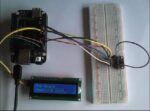
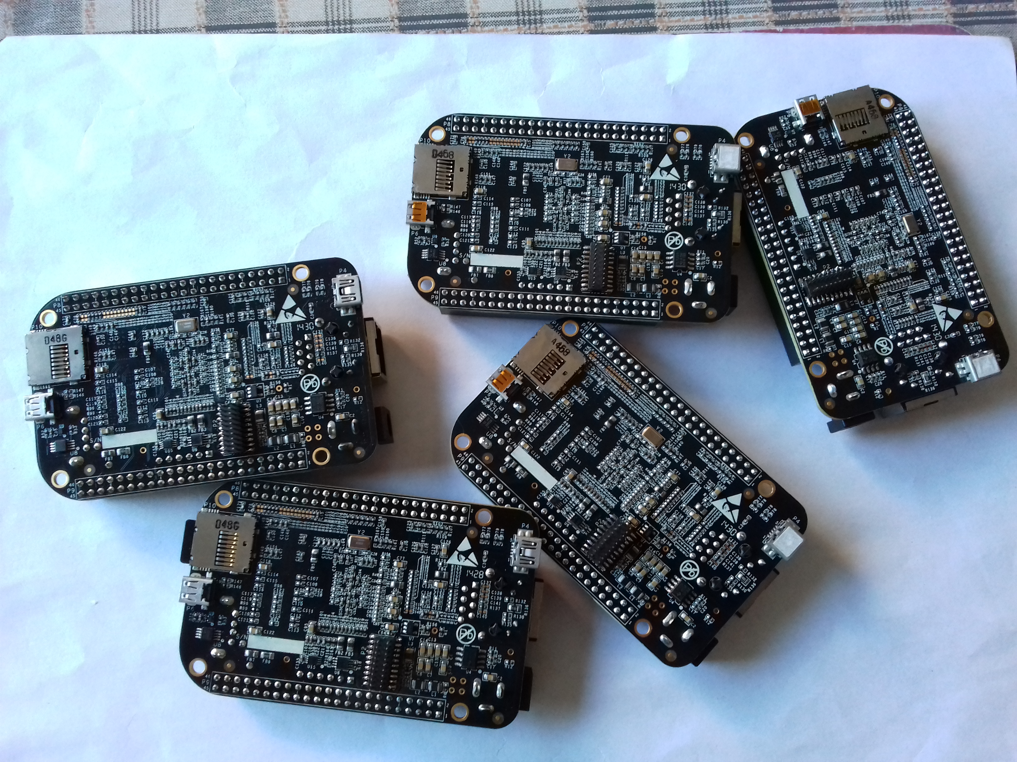
I initially settled on the Raspberry Pi as was familiar with the board and it seemed to tick all the boxes. I then discovered that JTAG has to be enabled after boot (Raspberry Pi JTAG), which didnt fit with one of the labs I was planning, more on the labs later. After looking around I settled on the BeagleBone Black, going forward referred to as BBB. I purchased a few, some SPI LCD Screens, SPI Flash Chips (W25Q16B) and breadboards. OK, the plan now was to hookup the LCD screen and Flash Chip using the SPI breakouts on the BBB and then enable 2 x SPI (only 1 is enabled by default) on the BBB to drive the LCD and Flashchip. Once achieved, I then programed the flash chip with “Hardware Hacking 2018”, along with some other info the sudents would discover while sniffing the SPI bus. During initialisation the BBB would read the message off the flash chip and write it to the LCD. That was the basis of my IoT device for the students to play with. The outline of how I did this will follow.
The BBB has a 6 Pin header already attached that supports UART, so no need to do anything there. The JTAG port on the BBB is on the bottom of the board and requires a surface mount 20 pin header to be added. As I’d already decided no soldering for students, I would have to attach the headers to all the student boards, not a biggy, took a couple of hours and done.
OK, that was pretty much all I had to do physically to the BBB, we will get to the software config in a bit. The processor on the BBB is a Sitara AM335x, so a suitable JTAG debugger was required and software to drive the labs I had in mind. I settled on the TI XDS100v2 (spectrum digital also do one), the segger Jlink would have sufficed but as the XDS100v2 worked better with CSS (Code Composer Studio), the software I had chosen to support the debug session. On an aside, CSS allows the creation of a debug session without having the associated code project to hand to debug. As it turned out with the XS100v2 I could access the Sitara RAM while the processor was running but with the segger jlink the processor has to be halted.
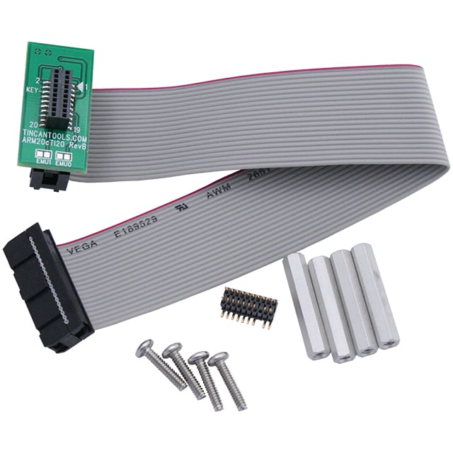
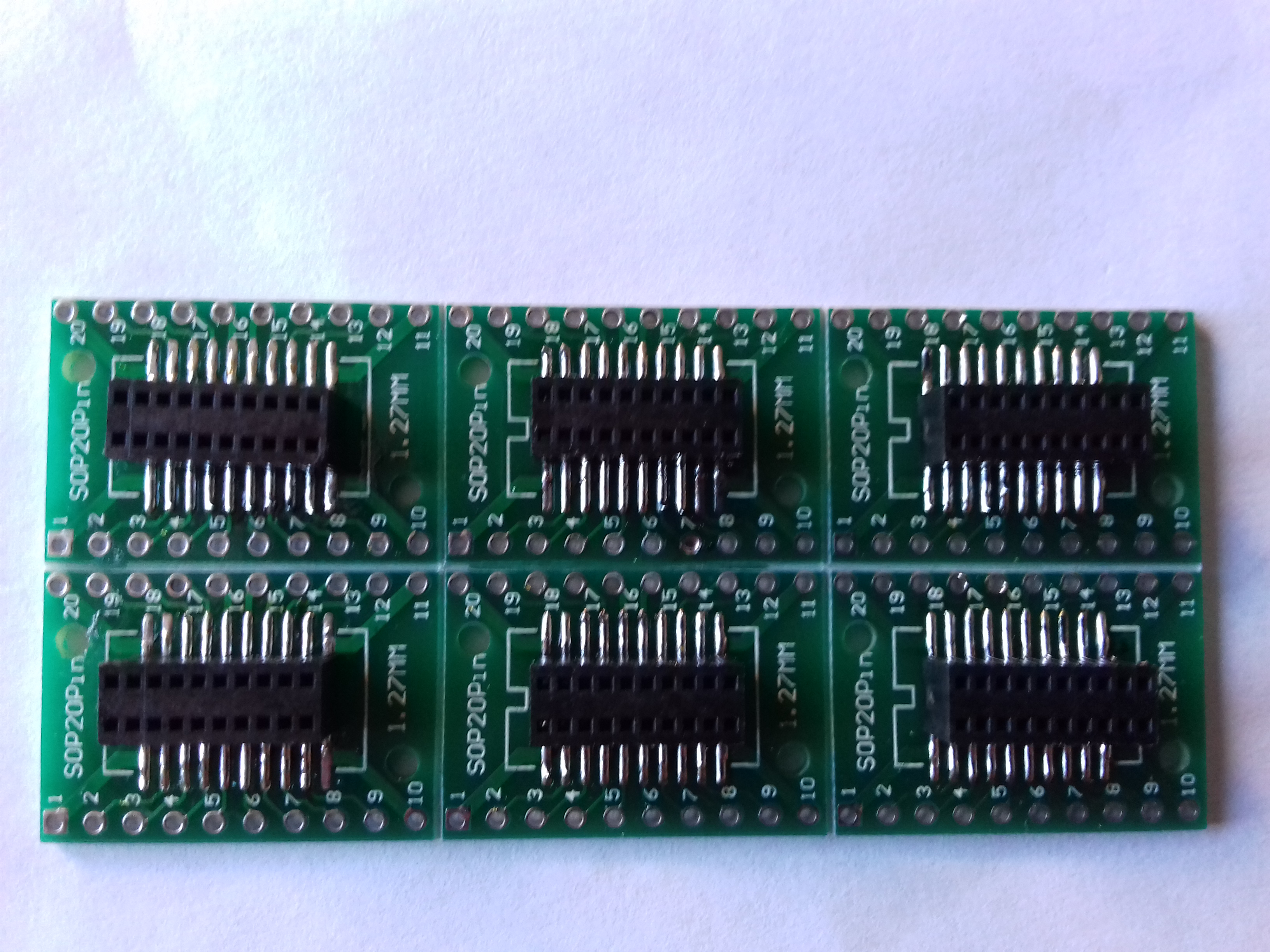
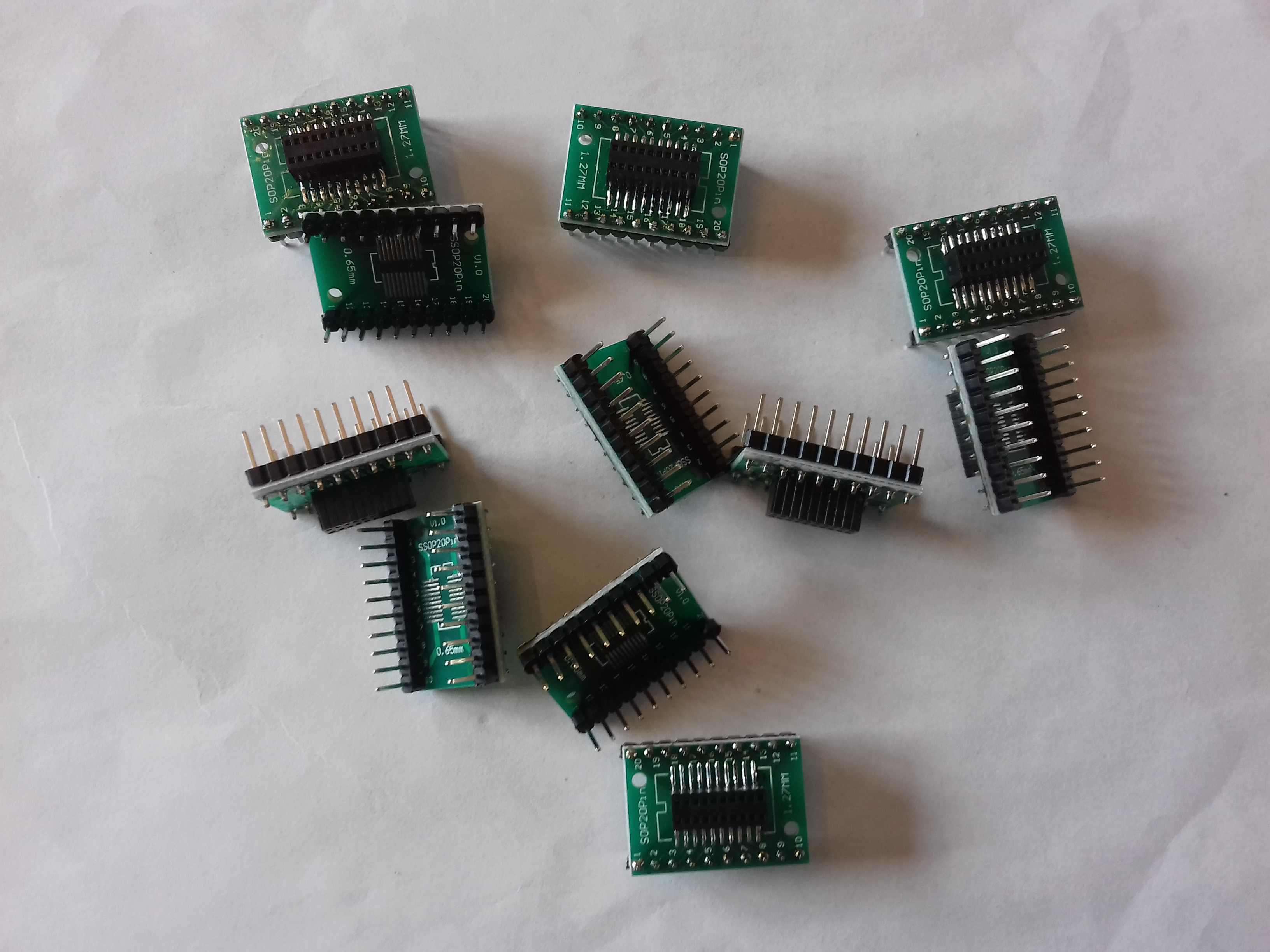
OK, so now I am after a lead/cable to convert the CTi20 (mini 20 pin header) to something the XDS100v2 could handle. The commercial converter cables in the UK are circa £99, I wasnt going to spend that on cables, so I decided to make my own from using breakout boards. For a £37 investment (SOP20 breakout board, 2.54mm pins and M52-5151045 female sockets) I was able to make 10 of my own. The only thing these converters didnt have was the key pin, this pin ensure correct orientation when plugging in the ribbon cables, something the students would have to figure out themselves 🙂
I bought the SOP20 breakout boards, few pence, and the female headers (M52-5151045 ) and soldered them together, the soldered on the std 2.54mm pin so the students could jumper the BBB JTAG to the XDS100v2. Which is something they would probably do in the real world as very few devices come with a nice header to plug onto, although some do!
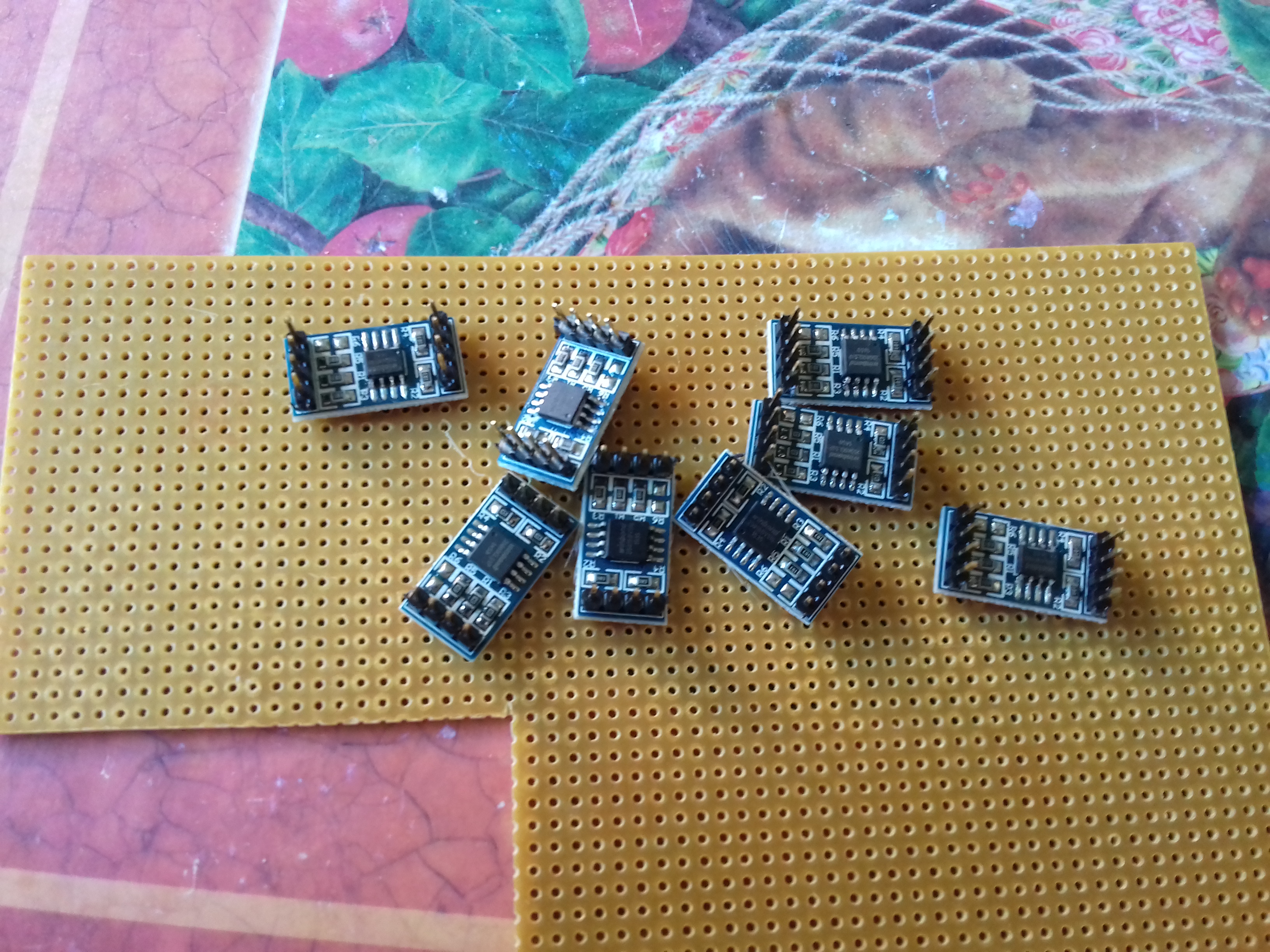
OK, onto the flashchips, I purchased those already mounted on a PCB and just had to solder on the 2.54mm pins to mount them on the breadboard.
Really pleased with the student kit and labs that I had in mind, it was time to work on the course content. This was easier than I thought, it was just a dump of everything I knew, the challenge was to structure the content in a logical order to deliver as a course. I had to keep in the front of my mind that students may have no experience of hardware hacking or infact digital electronics. I also wanted to add a commercial element, that would reflect an impact on decisions made during the course. The scenariois is that the students work for Widget IoT company and are testing the companies new product. For every vulnerability we find, we discuss the remediation and then the impact (time and money) of the remediation options. If you wanna know how this works, come on the course.
Lets finish Pt1 there as we’ve covered all the physical stuff, Pt2 we’ll look at the software config changes to the BBB, programming the FlashChip and making SSD install cards, once we have a functional, hardware and software, student kit.

